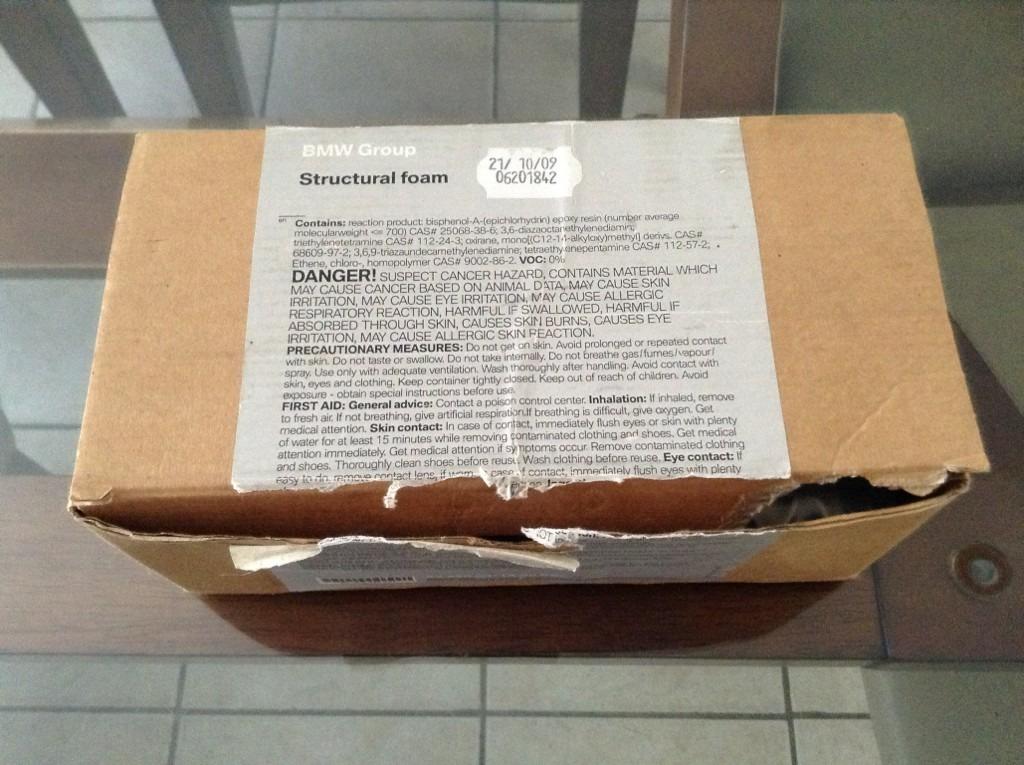
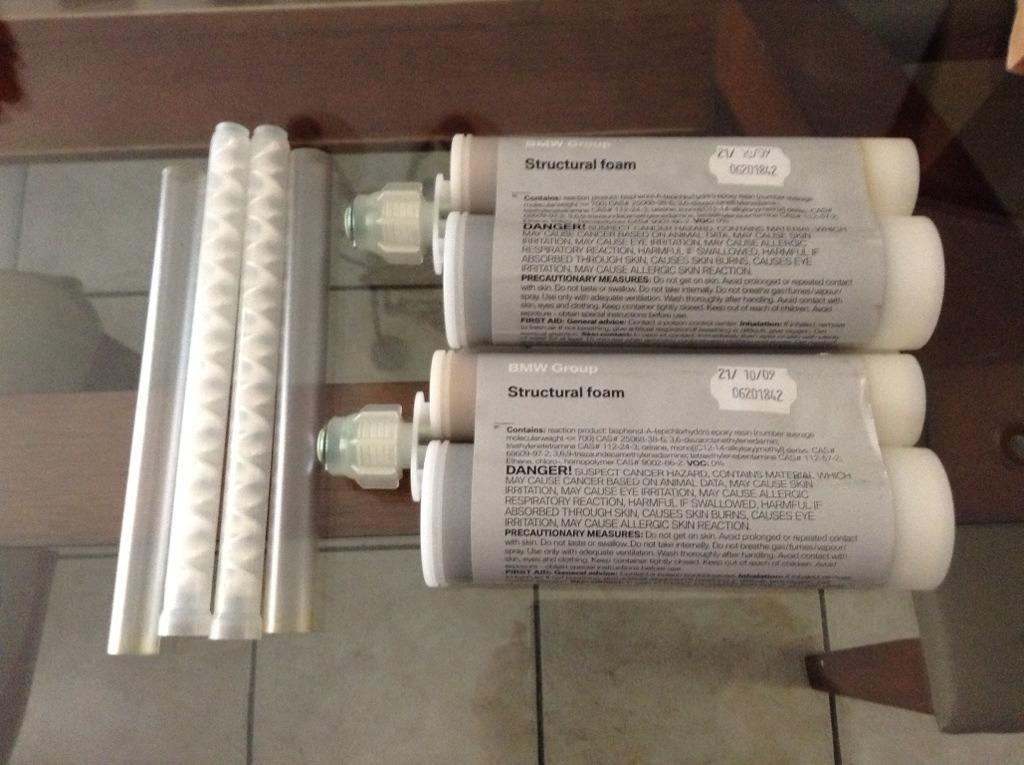
A lot of the discussion in this thread has been about how many tubes of foam to inject, which holes to inject it into, which layers to inject it into, whether cavity foam is required and if so, where it should be injected. Some of uncertainty arose when people started to look closely at BMW's original procedure and question it. Also, conflicting information has been posted in various forums.
Since there's so much conflicting information and injecting foam is irreversible, I decided to take a look at this to satisfy myself how it should be done before I do it. I wish I had an uninstalled RACP to inspect, but since I don't, I looked for photos. There are a lot of photos, but unfortunately, most are of the rear mounts. There aren't very many useful photos of the front mounts. I used images from M3F (
here and
here), as well as from posts on
www.vrperformance.com,
www.e46zone.com,
m3cutters.co.uk and
aussieexotics.com. Thanks to those who posted the photos, especially maruscmn and thomn8r.
Since there are so many good photos of the rear mounts, I started there.
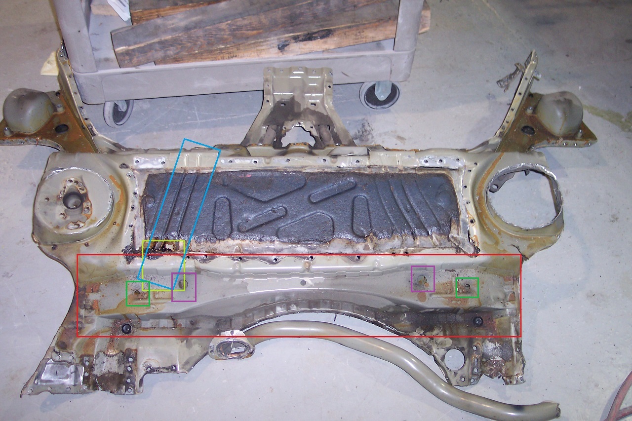
Below is a photo of an "original" coupe RACP. I've highlighted some notable areas.
In the red, you can clearly see that at least in this view, the driver and passenger side rear mounts appear to be mirror images of each other. Without cutting an RACP open, I have no way to confirm if they are mirror images inside, but I'd be surprised if they aren't. I think it's safe to say that the claim that the passenger side mount is different can be disregarded. Based on this photo, the procedure for injecting foam into the rear mounts should be the same for both sides, at least for the original design RACP.
In the yellow, you can see that if there is a passage from the cavity between the rear mounts to the cavity between the front and rear mounts (the blue area and the corresponding area on the passenger side), it's quite small. Again, there's no way to confirm how big the passage is without cutting an RACP open.
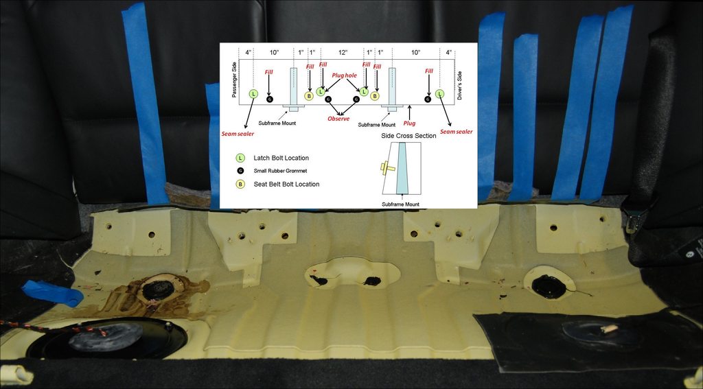
Based on this photo, in my opinion, the best places to inject foam in the rear mounts are the smaller outer openings on the driver and passenger sides (highlighted in green). My reasons for this are because the areas to the far left and far right are small volume, closed off (the foam has nowhere to go) and the two openings are very close to the mounts. If all of the foam is injected into these openings and allowed to flow inward from either side, the mounts will be completely encapsulated and any air pockets will be pushed in one direction, inward. It would be useful to know what the volume of the cavity is to confirm the amount of foam required. When / if I inject foam into the RACP on my car, I will probably close off the larger openings (highlighted in purple) to force the foam to stay within the internal cavity. I think this makes sense, because the load on the rear mounts is tension (particularly on the driver side), so putting foam above the structure doesn't serve any purpose, whereas filling the entire lower cavity with foam will distribute the load all the way across the RACP instead of only toward the sides.
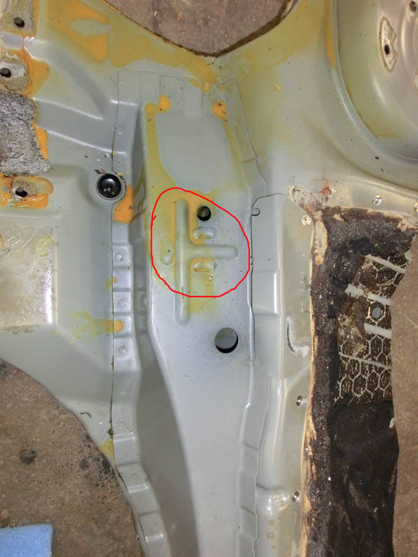
Here is a close-up of the driver side rear mount. The highlighted area is on the original, but note the area where the passage to the front mounts is located. If there is an opening between the internal cavity of the rear mounts, it's small.
Below is a photo of a new RACP. I highlighted the major difference, which is what appears to be a barrier inside the rear cavity on the driver side.

Here are a couple of close-up photos showing the difference. If it's a barrier, as suspected, then it will prevent foam from flowing toward the inner part of the rear mount structure. Perhaps the additional spot-welds noted by Redish are an improvement, but I don't think this barrier (if that's what it is) is an improvement. Since most people are injecting 2 x 420 ML into this cavity, it would be useful to know what the volume is. It would also be useful to know where excess foam would try to exit the cavity if too much is injected. If someone wanted to completely fill the rear cavity all the way across, it would might have to be done from the passenger side, depending on how tightly the barrier seals the cavity (assuming it is a barrier).
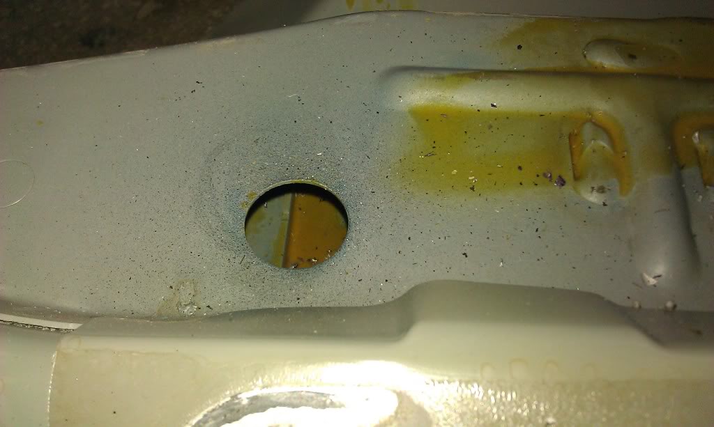
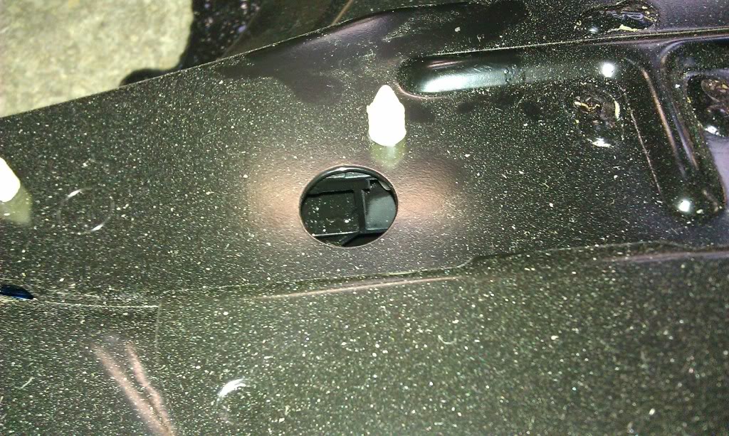
Below is a photo of the driver side rear mount inner cavity. You can clearly see that if foam is injected to the left of the mount, it will easily flow through the mount, fully encapsuutf8g it.
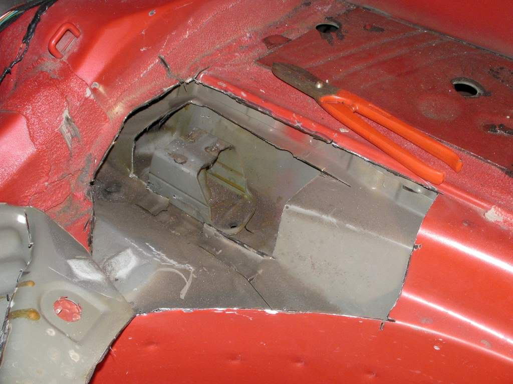
Below is the only photo I've found that shows the entire front of the RACP from above. If anyone knows of a better photo, please let me know. Unfortunately, the quality isn't very good, but you can see the layer that forms a cavity around the front mounts. It's not completely clear from the photo, but it appears that the passenger side and driver side cavities are not connected. It also appears that there is no barrier between the area under the rear seat and the cavities to the left and right where the RTABs are located. Those cavities are quite large and it would be wasteful if foam migrated into them, so it makes sense that a substantial amount of cavity foam should be injected into the openings on the outer sides of the seat.
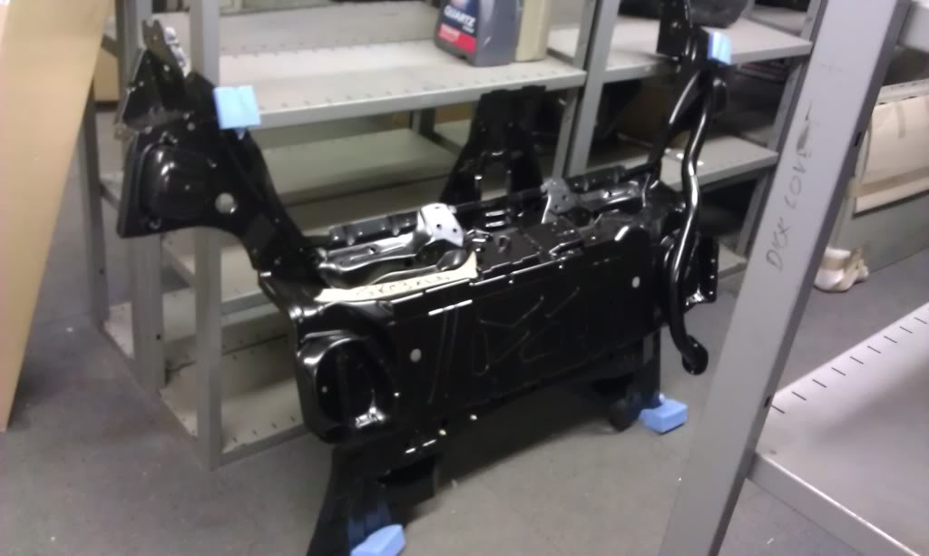
Below are photos of the front passenger side mount. The red area is the passage from the cavity above the front mount to the cavity between the front and rear mounts. The yellow area is the seatbelt bolt hole. The blue area is an internal hole that is not externally accessible, which is unfortunate, because it otherwise would be an ideal place to inject foam directly into the mount. Since the load on both sides is compression, I think it's beneficial to completely fill the front mount cavity.
Below is a photo of the front passenger side mount looking front to back.
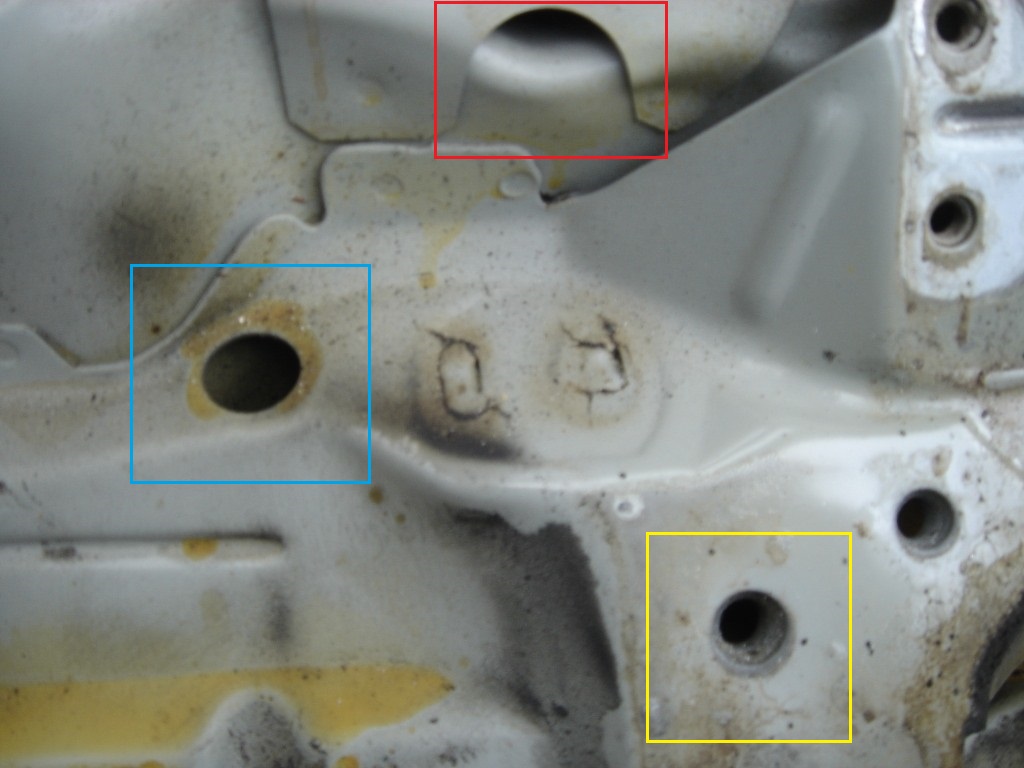
Below is a photo of the front passenger side mount looking down from above. The red highlight around the mount is from the original photo.

Here is a photo of the seat area looking back to show the openings where foam can be injected. Based on what I said above, I agree that the far left and right latch bolt holes should be injected with cavity foam to prevent the structural foam from migrating into the cavities where the RTABs are located. I also agree that structural foam should be injected into the next inner most holes until it appears at the seat belt bolt hole. After that, I think foam should be injected into the seat belt bolt holes until it starts to leak out of the latch bolt hole, at which point the latch bolts should be replaced and foam injected until it appears at the middle holes. I don't see any point to also inject into the latch bolt hole because it's so close to the seat belt hole.
Quite a lot can be determined from photos, but the only way to determine the volumes of the various cavities is to take measurements from an RACP that is still fastened to the surrounding panels. Unfortunately, due to the way the RACP fastens to the surrounding panels, a lot of the metal would have to cut out. Basically, from the front edge rear seat where it joins the floor, across to either side, all the way back around the wheel wells and back across the trunk through the middle of the "spare tire well'. When I first asked an autowrecker how much they would charge for the labour to remove an RACP they said $300, but I suspect it would be more based on how much of the surrounding panels would have to be removed to preserve the volumes of the cavities. If anyone would like to see this done and you are willing to share the cost, send me a PM. I'm willing to do the work, but not to part with $400 or more.


 Απάντηση με παράθεση


